|
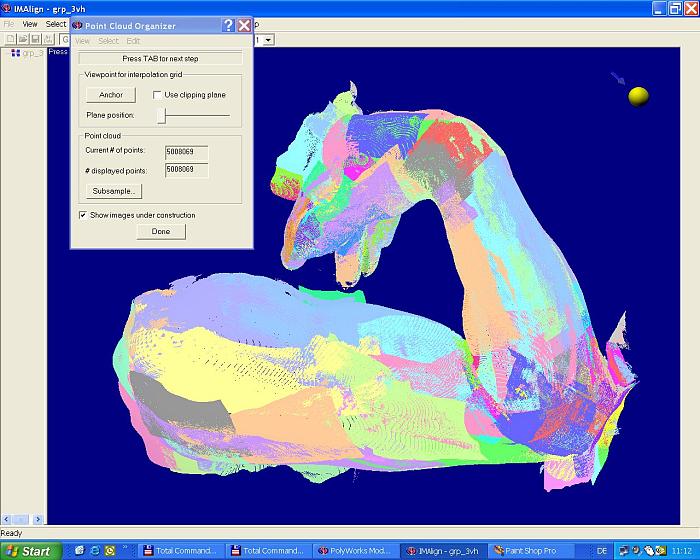
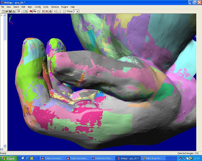
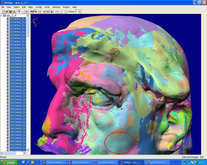
Using IMAlign , the fitting of the scan stripes acquired with the ModelMaker
XP/Faro Gold Arm equipment data could be
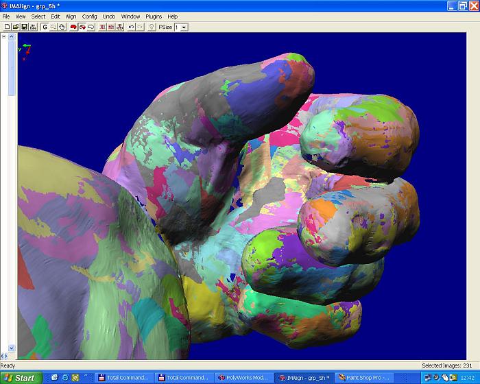
noticeable improved. After only two iterations, the scan stripes were
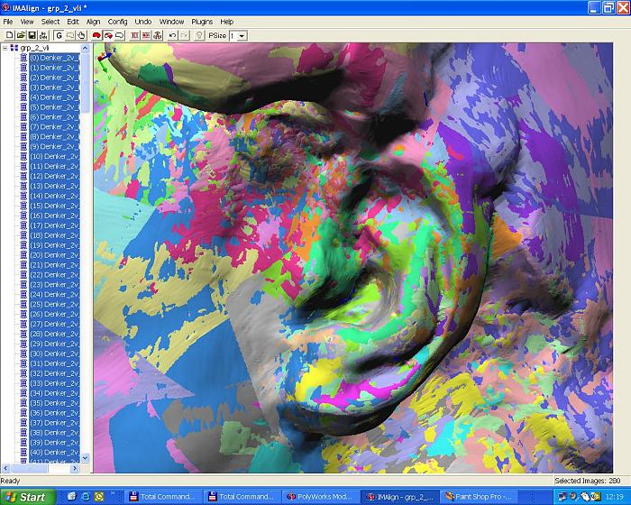
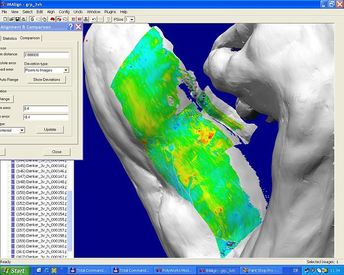
intertwined much better (Ill. 2) The improvement could be checked by measuring the fitting quality in
PolyWorks Inspector. Green and turquoise areas indicate optimal fitting;
only very few cleavages remain (orange and red areas) - with red areas
indicating a deviation as small as of 0.4 mm (Ill. 3).
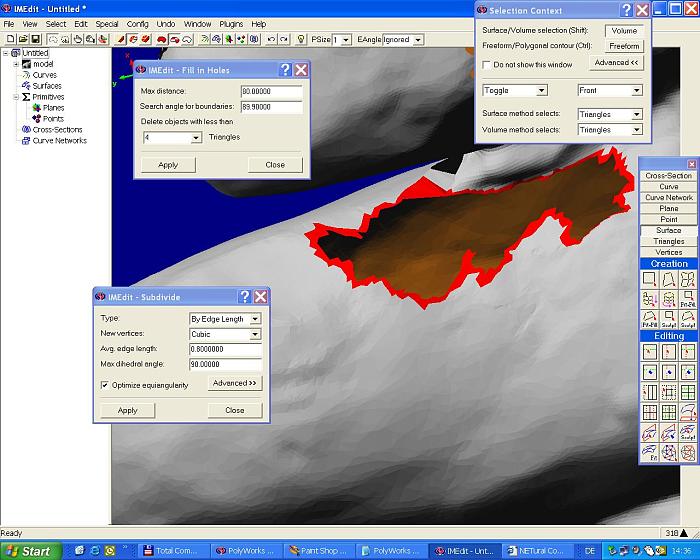
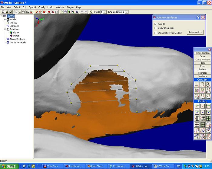
We were also able to inspect any remaining small
holes, for example between the fingers of the sculpture. During our
session, Dr Duwe demonstrated us again how such minor deficiencies can
be repaired using PolyWorks IMEdit (Ill. 6 and 7). The newest version V.8 even allows
for automatic filling of holes by means of curved Béziers surfaces. By
masking and isolating single parts of the sculpture, we we able to
view and edit single surfaces that normally are occluded by other parts.
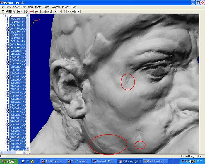
A closer view of our virtual model also revealed a
series of very slight artefacts, e.g. traces of uneveness in the
surface of single scan stripes,
mainly caused by a - very small - slackness of the Faro Gold Arm during the scan
movement (Ill. 8 and 9). Although such deviations from the ideal plane amounted only to ca. ±20 microns, we hoped to reach even better
results with the ModelMaker System as soon as the new Faro Platinum Arm
had been released.
WILL BE CONTINUED
|